Electrical Architecture
This page outlines the low-voltage (LV) systems, safety circuits, board microcontrollers, and tractive system container (TSAC) of the ART26 Formula Student vehicle.
1. High-Level LV Architecture Diagram
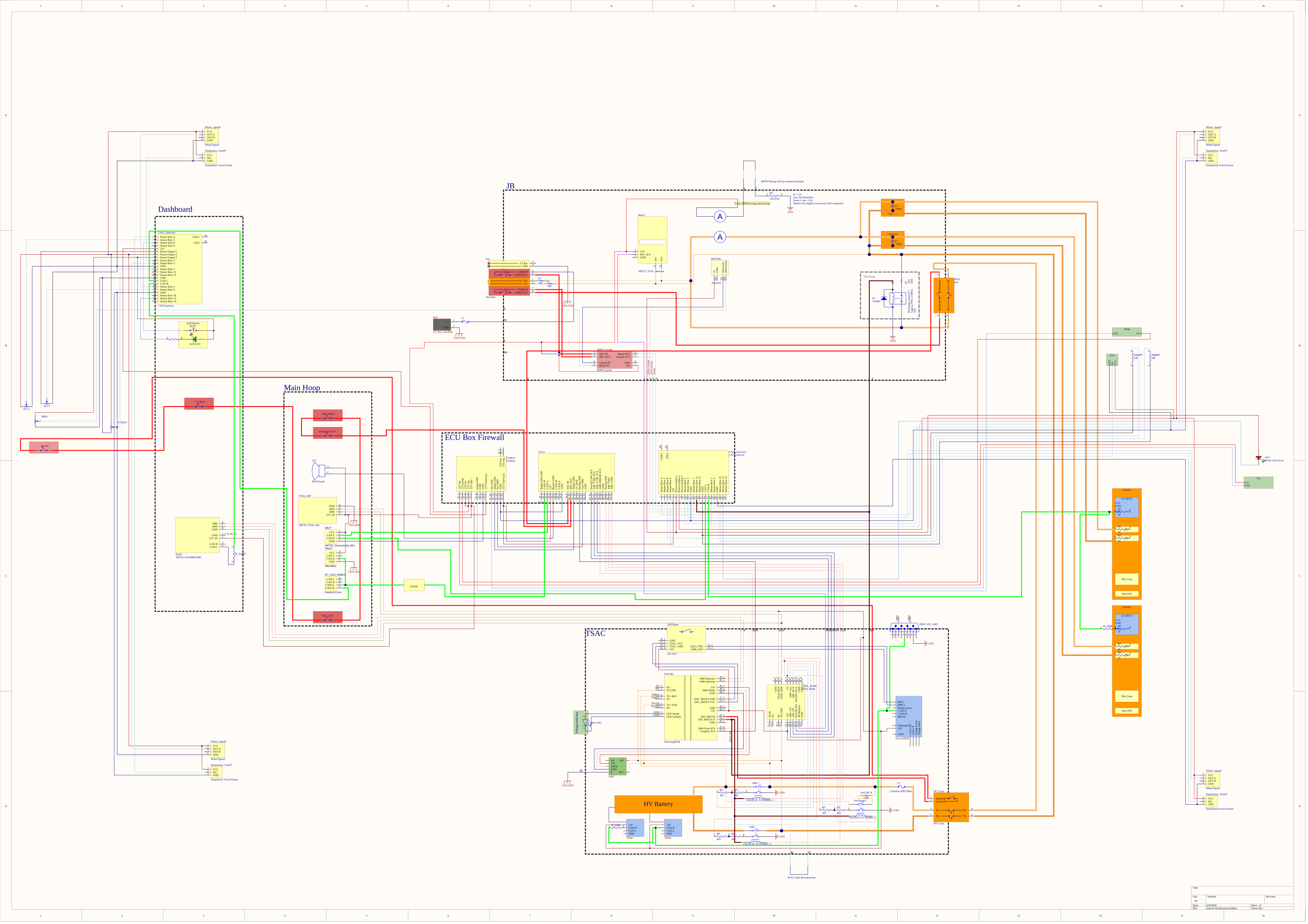
The diagram below details the interconnection between the 12V battery system, control units, safety modules, and the Tractive System Accumulator Container (TSAC). All control units communicate via a shared High-Speed CAN bus (indicated by the green CAN node line).
.png)
1.1 Low-Level Overview
2. Low Voltage (LV) Power Domain
12V Accumulator System
- Power Source: 12V low-voltage accumulator.
- Monitoring: Controlled by the LV SoC board (powered by an STM32L5 microcontroller), which manages cell SoC (State of Charge), current, and voltage monitoring.
- Distribution: Connects from
LV Battery Connector IN->Main Fuse->LV Battery Connector OUTto feed the FuseBox and distributed control units.
FuseBox
- Houses system fuses and manages:
- Inrush Current Limiting: Prevents damage to downstream control units during power-up.
- Feedback Voltage Limiting: Regulates spikes.
- Cooling Control: Works in tandem with the ECU to drive fans and pumps.
3. Distributed Control Units & Microcontrollers
All primary boards are equipped with specific STMicroelectronics microcontrollers tailored to their processing and peripheral needs:
| Board | Microcontroller | Key Responsibilities |
|---|---|---|
| ECU | STM32H5 | Vehicle FSM, Control FSM, Cooling Control, NMOS AIR Control, AMS Error Filtering, CAN BMS Node |
| Telemetry | STM32H5 | RTK GPS processing, CAN BMS Node, LTE Router interface, SD Card Logging |
| Dashboard | STM32H5 | TFT LCD Display driver, CI SCS LEDs |
| Gateway Front | STM32G4 | Oversampling ADCs, Selectable voltage dividers/filtering, Fused power distribution |
| Gateway Rear | STM32G4 | Oversampling ADCs, Selectable voltage dividers/filtering, Fused power distribution |
| LV SoC | STM32L5 | Battery voltage, current, and SoC monitoring |
| Inverters (Left/Right) | STM32L5 | CAN Node interface, UART-to-RS232 conversion for programming |
4. Tractive System Accumulator Container (TSAC)
The TSAC houses the high-voltage cells and critical safety/control electronics:
- BMS (Battery Management System): Interfaces with dual Thermistor Expansion Modules to monitor cell temperatures.
- IMD (Insulation Monitoring Device): Continuously measures insulation resistance between the HV tractive system and the LV chassis ground.
- TSAL Main and Measure: Handles TSAL plausibility, Safety Control System (SCS) checks, and generates the RED/GREEN TSAL status signals.
- Precharge PCB: Includes the voltage indicator, a 95% precharge comparator, and AMS/IMD error latching.
- SDC Sync PCB: Used to synchronize SDC resets triggered by the physical
ERROR CLEARbutton. - Contactor Assembly: Features the main fuse, current sensor, Accumulator Isolation Relays (
AIR+,AIR-), and a precharge relay/resistor circuit feeding theMAIN HV CONNECTOR.
5. Junction Box & Safety Circuits
Junction Box
Bridges the high-voltage tractive system power with the inverter units:
- BSPD (Brake System Plausibility Device): Shuts down the tractive system if braking and high power throttle (>5kW) occur simultaneously. It does not perform latching, but holds the SDC open for 10 seconds after the error is cleared.
- TSAL Measure (TSAL RED): Reads the high-voltage levels at the inverter input capacitors and controls the RED TSAL warning light.
- Discharge Relay: Bleeds the high-voltage inverter capacitors down below 60V within 5 seconds of shutdown.
- Data Logger & Current Sensor: Measures tractive system power draw.
Physical Safety Switches (SDC Loop)
The shutdown circuit loop integrates mechanical switches that instantly cut power to the AIR contactors if triggered:
- BOTS (Brake On-Over Travel Switch): Mounted near the pedal box to trigger if the brake pedal travels beyond its mechanical limit.
- Inertia Switch: Triggers if the vehicle experiences an impact above a specified G-force threshold.