Software Architecture
This page outlines the software modules, sensor feeds, and control flows running on the ART26 Formula Student vehicle.
1. High-Level Software Architecture Diagram
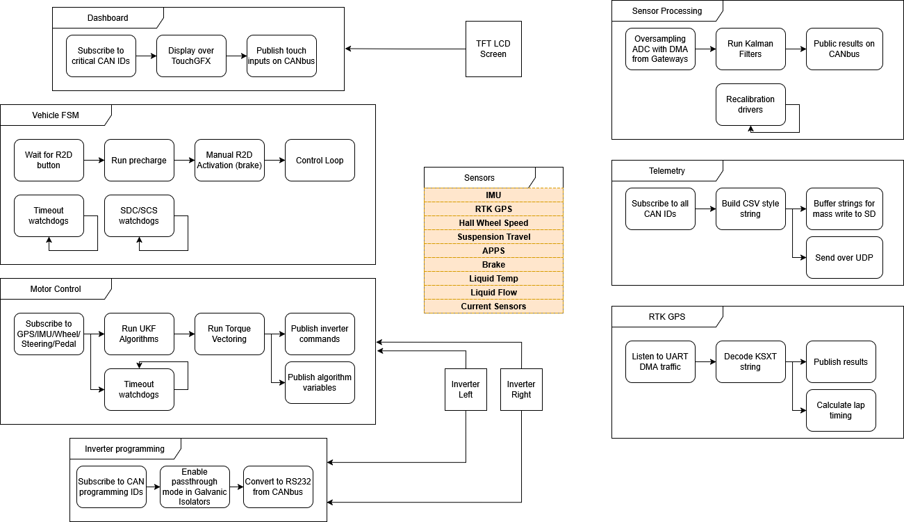
The software architecture is divided into decoupled functional blocks that communicate asynchronously via the CAN bus.
2. Core Software Functional Blocks
Dashboard
- CAN Interface: Subscribes to critical CAN IDs from other boards.
- UI Engine: Renders the driver screen over TouchGFX for a high-refresh TFT LCD Screen.
- User Inputs: Publishes touch panel inputs back onto the CAN bus (e.g. settings changes, page navigation).
Vehicle FSM
Manages the safety-critical state machine transitions of the vehicle:
- Startup Sequence:
Wait for R2D (Ready to Drive) button->Run precharge->Manual R2D Activation (brake + button)->Control Loop. - Diagnostics: Runs background tasks for
Timeout watchdogsandSDC/SCS watchdogsto instantly catch sensor implausibilities or communication loss.
Motor Control & Torque Vectoring
Runs real-time traction and stability control algorithms:
- Inputs: Subscribes to GPS, IMU, Wheel Speeds, Steering Angle, and Pedal Position sensors.
- UKF Algorithms: Runs Unscented Kalman Filter algorithms for vehicle state estimation (slip angle, velocity, etc.).
- Torque Vectoring: Calculates individual torque targets for the Left Inverter and Right Inverter to optimize cornering dynamics.
- Outputs: Publishes inverter commands and internal algorithm variables for logging.
- Safety: Runs dedicated
Timeout watchdogsto shut off inverter torque if command packets are delayed.
Inverter Programming
Provides a diagnostics interface to flash or configure the inverters:
- Subscribes to CAN programming IDs.
- Enables passthrough mode on the Galvanic Isolators.
- Converts CAN bus commands to RS232 communication directly required by the inverter programming interface.
Sensor Processing
Processes raw analog signals from physical gateways:
- Uses DMA (Direct Memory Access) to perform oversampling of ADCs from Gateways without blocking CPU execution.
- Runs Kalman Filters to denoise sensor signals (like suspension travel and throttle inputs).
- Publishes refined physical values onto the CAN bus.
- Integrates runtime
recalibration driversto tare sensors on the fly.
Telemetry & Logging
Ensures all vehicle data is recorded and broadcasted:
- Subscribes to all CAN messages.
- Builds a formatted CSV-style telemetry string.
- SD Logger: Buffers the CSV strings in RAM for high-throughput write operations to the physical SD Card.
- Wireless Broadcast: Packages and transmits telemetry packets over UDP to the pit lane receiver via Wi-Fi/LTE.
RTK GPS
- Listens to UART traffic using DMA to offload parsing overhead.
- Decodes the custom KSXT NMEA sentences.
- Publishes precise vehicle coordinates, heading, and speed on the CAN bus.
- Computes real-time lap timings on the board.
3. Monitored Sensors List
Our control units ingest and process data from the following sensors:
- IMU (Inertial Measurement Unit): 6-DOF acceleration and angular rates.
- RTK GPS: Centimeter-level positioning and heading.
- Hall Wheel Speed Sensors: Angular speeds of the four wheels.
- Suspension Travel Sensors: Linear potentiometers to measure damper displacements.
- APPS (Accelerator Pedal Position Sensors): Dual redundant throttle sensors.
- Brake Pressure Sensors: Front and rear brake line pressures.
- Liquid Temp Sensors: Coolant temperatures in the motor and accumulator loops.
- Liquid Flow Sensors: Flow rates in the cooling loops.
- Current Sensors: High-voltage tractive system and low-voltage battery currents.